Four-stroke engine

Image result for 4 stroke engine animation


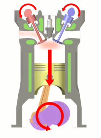
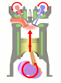
Four-stroke cycle used in gasoline/petrol engines. 1 = Intake, 2 = Compression, 3 = Power, 4 = Exhaust. The right blue side is the intake port and the left brown side is the exhaust port. The cylinder wall is a thin sleeve surrounding the piston head which creates a space for the combustion of fuel and the genesis of mechanical energy.


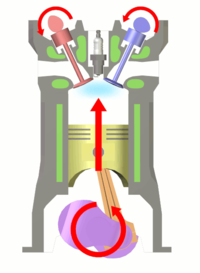
Top dead center, before cycle begins 1 – Intake stroke 2 – Compression stroke
                                              Starting position, intake stroke, and compression stroke.
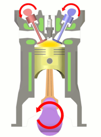
Fuel ignites 3 – Power stroke 4 – Exhaust stroke
                                        Ignition of fuel, power stroke, and exhaust stroke.

Comments

Popular posts from this blog

Hydraulic Brake System Diagram

Fig: Hydraulic Brake Diagram

Mazda 6 Wagon Lighting System

Automobile Department All Book Pdf File Free Download

Book Review by Automobile Book  Pdf File Free Download Click on the link below to review the article in its entirety - PDF file  Download.